Derui chamber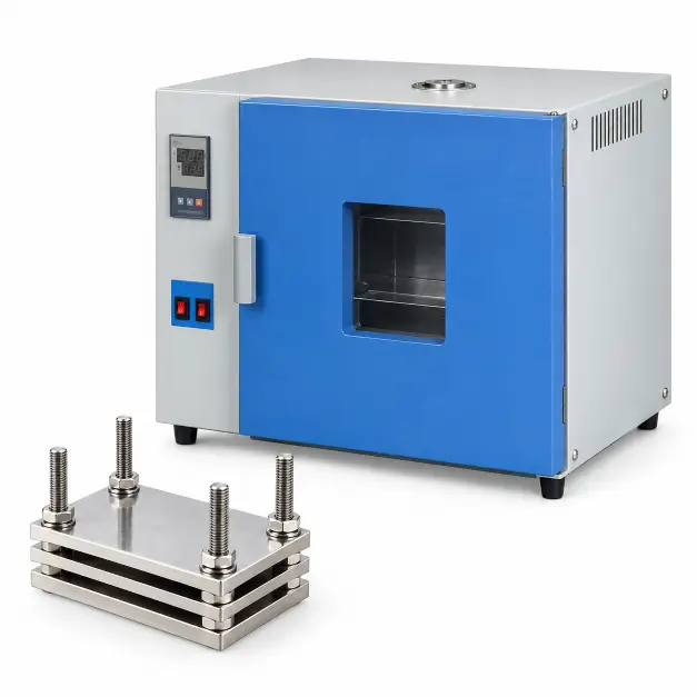

 Message
Measure Permanent Thickness Loss After Heat and Compression
The DR-J204 combines a forced-air laboratory oven with a constant-deflection stainless-steel fixture to evaluate how much flexible foam fails to recover after prolonged compression. Interchangeable spacer blocks establish the required deflection mechanically, while controlled heating, timing and post-test recovery support repeatable compression-set measurements for foam production and laboratory quality control.
Complete Oven + Fixture System
Run the elevated-temperature exposure and constant-deflection step with one specified system instead of sourcing an oven and heat-resistant fixture separately.
Mechanical Compression Control
Precision spacers set the plate gap for 50% or 75% compression without relying on air pressure, force control or operator-estimated travel.
Production-Relevant Results
Quantify permanent thickness loss in mattress cores, sofa cushions, seating foam and other flexible cellular materials after a defined thermal-compression cycle.
1. What the DR-J204 Measures
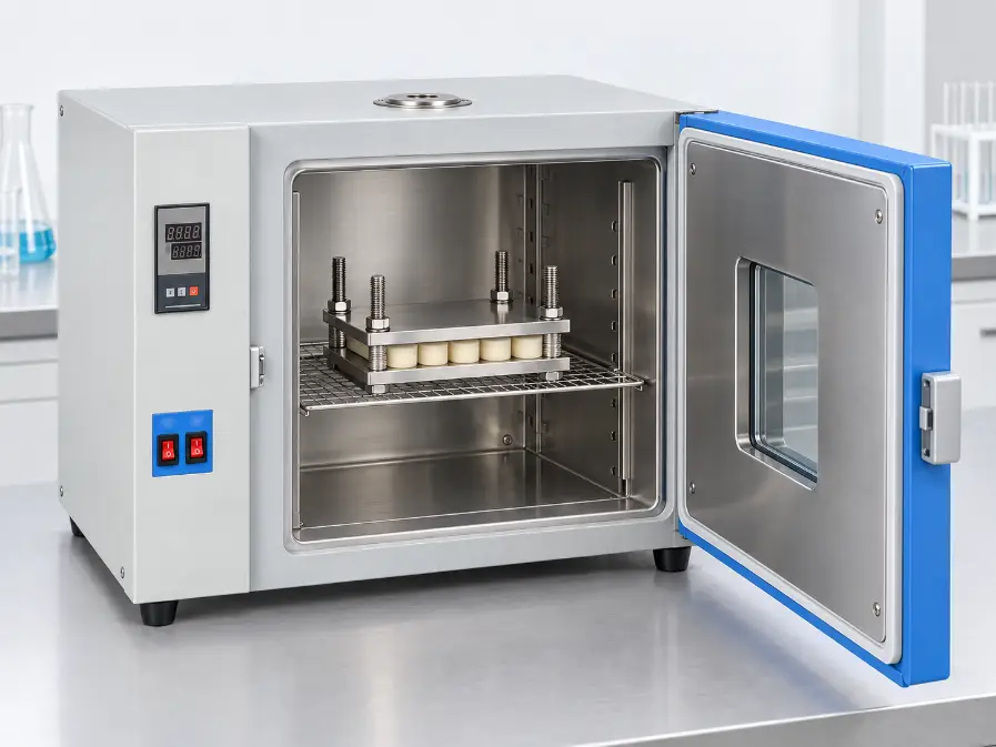
Foam can feel acceptable during an initial hardness test yet lose height after it remains compressed in a mattress, sofa cushion, automotive pad or upholstered seat. Compression set expresses the permanent thickness loss that remains after a specimen is compressed for a specified time and temperature, released, allowed to recover and measured again.
The DR-J204 is intended for flexible polyurethane foam, latex foam and other compatible cushioning materials covered by the selected method. It is different from an IFD/ILD hardness tester, which measures load-bearing resistance during indentation, and from the DR-J802 dynamic fatigue tester, which applies repeated compression cycles. Together, the three methods describe initial firmness, long-cycle degradation and permanent deformation under sustained compression.
2. How the Constant-Deflection Test Works
1. Condition and Measure
Condition the specimens in the atmosphere required by the selected method and measure the initial thickness, d0.
2. Install the Spacer Set
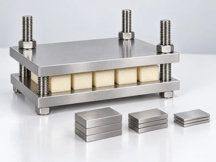
Place the specimens between parallel plates. Select spacers that mechanically limit the plate gap to the required percentage of the original specimen thickness.
3. Heat Under Compression
For the common Method A cycle, place the loaded fixture in the oven within the required transfer time and expose it at 70°C for 22 hours.
4. Release, Recover and Measure
Remove each specimen promptly, allow it to recover for 30 minutes under the specified conditioning atmosphere, and measure the recovered thickness, dr.
3. Spacer Selection for a 25 mm Specimen
The compression level is established by spacer thickness—not by adjusting load or pneumatic pressure. For a specimen with an original thickness of 25 mm, the nominal plate gap is calculated as:
| Compression Level | Nominal Spacer Thickness for 25 mm Foam | Method Position |
|---|---|---|
| 50% | 12.5 mm | Normal ISO 1856 Method A option; also used in applicable ASTM D3574 Test D specifications |
| 75% | 6.25 mm | Normal ISO 1856 Method A option where selected by the material specification |
| 90% | 2.5 mm | Special agreed condition; not presented as the default ISO Method A setting |
Five test pieces are evaluated for ISO 1856 reporting. They are specimens within a shared compression assembly, not five independently controlled machine stations. Specimens should be arranged with the separation and edge clearance required by the approved laboratory procedure.
4. Applicable Test Methods
| Standard | Relevant Scope | DR-J204 Configuration |
|---|---|---|
| ASTM D3574-25 Test D | Constant-deflection compression set of slab, bonded and molded flexible polyurethane foam | Heat-resistant parallel plates and interchangeable spacers used with the programmed oven exposure. |
| ISO 1856:2018 Method A | Compression set of flexible cellular polymeric materials at 70°C | Supports 50% or 75% compression, 22-hour exposure and 30-minute recovery; 90% only by special agreement. |
| GB/T 6669-2008 | Chinese method for compression set of flexible cellular polymeric materials | Configured around the selected compression level, temperature, duration and specimen preparation. |
| JIS K 6400-4 | Physical properties of flexible cellular materials, including compression set | Fixture and procedure must be confirmed against the laboratory’s purchased edition and material specification. |
5. Technical Specifications
| Parameter | DR-J204 Standard / Available Configuration |
|---|---|
| Model | DR-J204 Foam Compression Set Tester |
| System configuration | Forced-air laboratory oven with removable constant-deflection compression fixture |
| Standard temperature range | Ambient +10°C to 200°C |
| Optional temperature range | Ambient +10°C to 250°C |
| Typical compression-set temperature | 70°C; program according to the selected method |
| Typical exposure time | 22 h; adjustable timer 0–9999 min |
| Temperature fluctuation | ±1.0°C; high-precision configuration ≤±0.3°C |
| Display resolution | 0.1°C |
| Temperature uniformity | ±3% at the 100°C reference point |
| Control | Microprocessor PID temperature control with digital display; optional 7-inch touchscreen |
| Heating and circulation | Rear heating with forced-air fan and duct circulation |
| Oven chamber | 350 × 350 × 350 mm (H × W × D), nominal 30 L |
| Interior | Stainless steel |
| Exterior | Painted steel enclosure |
| Insulation | Compressed glass-fibre insulation |
| Shelves | 2 |
| Standard specimen | 50 × 50 × 25 mm |
| Reported specimen quantity | Five specimens for the ISO 1856 method; fixture arrangement is shared rather than independently controlled stations |
| Compression levels | 50% and 75% with dedicated spacers; 90% available for a specially agreed method |
| Fixture | Polished 304 stainless-steel parallel plates, interchangeable limit spacers and fasteners |
| Reference fixture set | 3 parallel plates, 24 spacers and 4 fasteners; confirm final spacer combination on the order specification |
| Thin-material accessories | Glass slides, 1–1.5 mm thick and 50–55 mm side length |
| Recovery period | 30 min; follow the tolerance and conditioning atmosphere stated in the selected method |
| Safety protection | Independent over-temperature protection and door-open pause |
| Optional measurement/reporting | Laser displacement sensor, 0.01 mm resolution, with automated PDF report configuration |
| Power supply | AC 220 V, 50 Hz, single phase |
| Rated heating power | 5 kW |
| Overall dimensions | 620 × 440 × 490 mm (W × D × H) |
| Operating environment | +5°C to +40°C |
Site-planning note: the final nameplate current, plug, cable and protective-device requirement must be confirmed on the approved electrical drawing before installation. No working-current value is published here because the previously supplied 14.5 A figure was not consistent with the confirmed 5 kW rating.
6. Compression Set Calculation and Reporting
For ISO 1856:2018, compression set is expressed as the percentage loss relative to the original specimen thickness:
- d0: original specimen thickness before compression.
- dr: specimen thickness after release and the specified recovery period.
A lower compression-set value indicates better thickness recovery under the reported condition. Results should include the compression level, exposure time and temperature—for example, compression set at 50%, 22 h and 70°C—because results from different conditions are not directly interchangeable.
The final test report should record the material identification, conditioning atmosphere, method and edition, initial and recovered thicknesses, individual values, median result, test conditions, deviations and test date. Laboratories should include the oven and thickness-measurement devices in their calibration and intermediate-check programme.
7. Selecting the Correct Configuration
| Information to Provide | Why It Matters |
|---|---|
| Material type and end use | Separates polyurethane, latex, viscoelastic and other cushioning-material requirements. |
| Required standard and edition | Determines the applicable conditioning, compression level, tolerances and report fields. |
| Specimen size and thickness | Confirms plate area, glass-slide requirements and spacer dimensions. |
| Compression level | Defines the required 50%, 75% or specially agreed 90% spacer set. |
| Temperature and exposure duration | Confirms whether the 200°C standard oven or 250°C option is appropriate. |
| Number of specimens per batch | Confirms fixture layout and whether additional fixture assemblies are required. |
| Thickness measurement and reporting | Determines whether manual measurement is sufficient or the optional displacement/reporting package is required. |
| Site electrical standard | Confirms the final power connection, cable, plug and protection arrangement. |
For laboratories planning several foam methods, use the Foam Testing Equipment category to compare hardness, dynamic fatigue and compression-set systems before specifying the laboratory configuration.
8. Frequently Asked Questions
What does a foam compression set tester measure?
It measures the permanent loss of foam thickness after the specimen is held at a defined compression level, temperature and duration and then allowed to recover.
Is DR-J204 the same as an IFD or ILD hardness tester?
No. IFD/ILD testing measures force during indentation. DR-J204 maintains a fixed deflection for a prescribed exposure period and measures the thickness that does not recover afterward.
How are 50%, 75% and 90% compression levels set?
Interchangeable spacer blocks mechanically establish the gap between the parallel plates. For a 25 mm specimen, the nominal gaps are 12.5 mm, 6.25 mm and 2.5 mm respectively.
Does ISO 1856 Method A require 90% compression?
No. ISO 1856:2018 Method A normally specifies 50% or 75% compression. A 90% level may be used only in special cases agreed by the relevant parties.
Why are five specimens listed instead of five test stations?
Five refers to the ISO test-piece quantity. The specimens share one compression assembly and the same plate gap; they are not five independently controlled machine stations.
Can thin foam materials be tested?
Yes, subject to the selected method. Thin pieces can be assembled with 1–1.5 mm glass slides, with the slide thickness accounted for when determining foam thickness.
Does the system automatically calculate the result?
The standard digital-temperature configuration controls the oven cycle. Automated displacement measurement and PDF reporting are optional; confirm whether your laboratory requires this package.
9. Related Foam Testing Equipment
- Foam Testing Equipment — compare systems for foam hardness, fatigue and permanent deformation.
- DR-J801 Foam IFD/ILD Hardness Tester — measure indentation hardness and support factor before and after conditioning.
- DR-J802 Foam Dynamic Fatigue Tester — evaluate thickness and hardness loss after repeated compression.
Configure the DR-J204 for Your Foam Test Method
Send the foam type, specimen dimensions, required standard and edition, compression level, test temperature, batch quantity and reporting needs. Derui will confirm the spacer set, fixture layout, oven configuration and electrical connection before quotation.